Triggering Modes (Manual, Digital, Sensor)
This page explains the five trigger modes available in the OV20i system and how to configure each for different inspection scenarios and automation requirements.
Overview of Trigger Modes
The OV20i offers five distinct triggering modes to accommodate various production environments and automation needs:
- Manual - HMI screen trigger
- Hardware - Electrical signal trigger
- PLC - Industrial controller communication
- Aligner Trigger - Automatic triggering when part alignment is detected
- Interval Trigger - Timer-based automatic triggering
Manual Trigger Mode
What is Manual Triggering?
Manual triggering allows operators to initiate inspections directly through the HMI interface using an on-screen capture button.
How it Works:
- Operator clicks Capture button in HMI interface
- Camera immediately captures and processes image
- Results display in real-time on HMI screen
Best Use Cases:
- ✅ Setup and testing - Recipe development and validation
- ✅ Low-volume production - Occasional quality checks
- ✅ Training and demonstration - Teaching operators system functionality
- ✅ Troubleshooting - Manual verification of inspection results
Configuration:
- Set trigger mode to Manual in Imaging Setup > Photometric Control
- No additional hardware connections required
- Accessible from HMI page capture controls
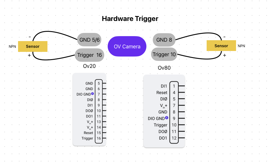
Hardware Trigger Mode
What is Hardware Triggering?
Hardware triggering uses electrical signals sent directly to the camera's digital input pins to initiate inspections.
Electrical Connection:
- Trigger Input Pin: Digital Input (DI) on M12 A-Coded 17 Pin connector
- Signal Type: Pull to GND to activate input
- Voltage: Compatible with 24V industrial systems
- Response: Immediate capture upon signal transition
How it Works:
- External device sends electrical signal to camera's trigger input
- Camera detects falling edge signal transition
- Inspection cycle initiates automatically
- Results available via digital outputs or communication protocols
Best Use Cases:
- ✅ High-speed production lines - Conveyor belt integration
- ✅ Sensor-driven systems - Proximity sensors, photoelectric sensors
- ✅ Simple automation - Direct electrical integration without PLC
- ✅ Retrofit applications - Adding vision to existing machinery
Configuration:
- Set trigger mode to Hardware in Imaging Setup > Photometric Control
- Connect trigger source to designated digital input pin
- Configure signal polarity and falling edge detection
PLC Trigger Mode
What is PLC Triggering?
PLC triggering enables sophisticated communication between the camera and programmable logic controllers using industrial Ethernet protocols.
Communication Protocols:
- Ethernet/IP - Allen-Bradley, Rockwell Automation PLCs
- Profinet - Siemens, Mitsubishi, Omron PLCs over Ethernet
- Industrial Ethernet - Universal connectivity for major PLC brands
Signal Flow Process:
- PLC Trigger Command - PLC sends trigger request to camera
- Trigger Acknowledge - Camera confirms trigger receipt
- Exposure Complete - Camera signals image capture finished
- Inspection Complete - Camera indicates processing finished
- Pass/Fail Result - Final inspection outcome sent to PLC
Advanced Features:
- Trigger ID Tracking - 16-bit rolling ID for correlation
- Busy Signal Monitoring - Camera status feedback to PLC
- Bidirectional Communication - Full data exchange capabilities
- Recipe Selection - PLC can switch between inspection recipes
Best Use Cases:
- ✅ Complex automation systems - Multi-station production lines
- ✅ Data integration - Manufacturing execution systems (MES)
- ✅ Recipe management - Automatic inspection switching
- ✅ Quality tracking - Detailed production reporting
Configuration:
- Set trigger mode to PLC Trigger in Imaging Setup > Photometric Control
- Configure network communication protocol
- Set up PLC logic for trigger sequencing
- Map data exchange parameters
Aligner Trigger Mode
What is Aligner Triggering?
Aligner triggering automatically initiates inspections when the template alignment system successfully locates and aligns a part within the field of view.
This is considered a software trigger mode and may not be ideal for all production scenarios.
How it Works:
- Template Matching - Camera continuously searches for alignment pattern
- Part Detection - Aligner locates part based on template regions
- Confidence Check - Alignment confidence exceeds threshold
- Automatic Trigger - Inspection initiates without external signal
- ROI Adjustment - Inspection regions align with detected part position
Template Configuration:
- Template Regions - Rectangle or circle patterns for edge detection
- Rotation Range - 0-180 degrees tolerance for part orientation
- Sensitivity - Edge-finding sensitivity adjustment
- Confidence Threshold - Minimum alignment confidence (0.6-0.9 recommended)
- Search Areas - Restricted regions for improved speed and accuracy
Best Use Cases:
- ✅ Variable part positioning - Parts not fixtured consistently
- ✅ Robotic presentation - Pick and place applications
- ✅ Flexible production - Multiple part orientations
- ✅ Automated feeding systems - Vibratory bowls, conveyors
Limitations:
- ⚠️ Software dependency - Relies on alignment algorithm performance
- ⚠️ Processing overhead - Continuous template matching affects speed
- ⚠️ False triggers - May trigger on similar but incorrect patterns
Configuration:
- Set trigger mode to Aligner Trigger in Imaging Setup > Photometric Control
- Configure template image and alignment regions
- Set confidence thresholds and search areas
- Test alignment reliability across part variations
Interval Trigger Mode
What is Interval Triggering?
Interval triggering automatically captures images at predetermined time intervals, useful for continuous monitoring and periodic quality checks.
How it Works:
- Timer Configuration - Set inspection interval (seconds, minutes, hours)
- Automatic Cycling - Camera triggers at specified intervals
- Continuous Operation - Runs independently without external signals
- Timestamp Logging - Each capture recorded with precise timing
Timing Options:
- Fixed Intervals - Regular periodic inspections
- Configurable Duration - Seconds to hours between captures
- Start/Stop Control - Manual override capabilities
- Schedule Integration - Potential integration with production schedules
Best Use Cases:
- ✅ Process monitoring - Continuous quality surveillance
- ✅ Slow-moving production - Low-frequency inspection needs
- ✅ Environmental monitoring - Periodic condition checks
- ✅ Data collection - Statistical process control sampling
Configuration:
- Set trigger mode to Interval in Imaging Setup > Photometric Control
- Configure interval timing parameters
- Set start/stop conditions
- Define data logging requirements
Trigger Mode Selection Guide
| Trigger Mode | Speed | Automation Level | Setup Complexity | Best For |
|---|---|---|---|---|
| Manual | Slow | Manual | Simple | Testing, Setup |
| Hardware | Fast | Medium | Medium | High-speed lines |
| PLC | Fast | High | Complex | Complex automation |
| Aligner | Variable | High | Medium | Variable positioning |
| Interval | Periodic | High | Simple | Monitoring |
Hardware Considerations
Electrical Specifications
- Voltage Range: 19-24 VDC input
- Signal Logic: Pull to GND to activate inputs
- Output Current: Max 100mA per output (when active, sinks to GND)
- Thermal Protection: Built-in thermal fuse for digital ground